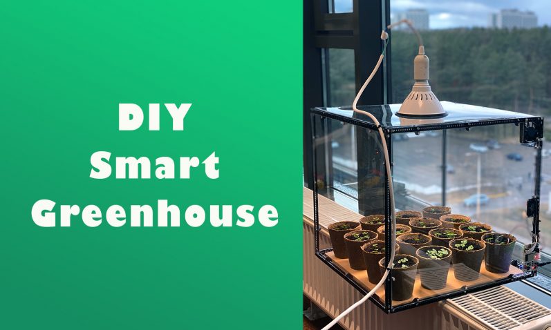
In this blog post we’ll continue our greenhouse project after our initial post available here. If you haven’t yet, read part 1 to explore the mechanical side of the smart greenhouse project. This time we’ll dive into the electronics side. Read on to get to know how to write firmware to read out soil and air conditions, and send these measurements out via WiFi. Additionally, we’ll also add remote control capabilities on the greenhouse, so we’re able to keep perfect conditions for our plants to grow.
Connecting electronics
As shown in part 1, we’ll be using programmable RoboBoard X4 as the central controller in this project. This board will collect sensor measurements, and communicate with a remote server as an IoT device. As we all know, it’s crucial to keep soil damp for the plants to grow, so we’ll add a soil humidity sensor from Sparkfun, and connect it via Qwiic interface to the RoboBoard X4.
Another important aspect is air temperature – keep it too cool or too hot and your plants will stop growing. For measuring temperature we’ll use Totem sensor board, which connects to the X4 board through TotemBus cable. For temperature regulation, we’ve added a small fan which is connected to X4’s integrated motor controller.
When everything is connected, schematics look like this:

Reading out sensors
Now that the hardware part is added, let’s do some coding! First, we’ll make sure that our sensors work and we can read out usable data from them. In the Arduino IDE, for reading Qwiic, which is basically I2C interface soil humidity sensor, Wire.h library will be used.
Soil humidity sensor
For the soil humidity sensor, we’ve connected it through GPIO connectors. Although RoboBoard X4 has a Qwiic connector built in, we didn’t have a matching cable, and had to make due with what he had at the time:
#include <Wire.h>

#define SOIL_COMMAND_GET_VALUE 0x05
const byte soilAddress = 0x28;

uint16_t soilHumidityRead(){
  uint16_t measurement;

  Wire.beginTransmission(soilAddress);
  Wire.write(SOIL_COMMAND_GET_VALUE); // command for status
  Wire.endTransmission(); // stop transmitting //this looks like it was essential.
  Wire.requestFrom(soilAddress, 2); // request 1 bytes from slave device qwiicAddress
  while (Wire.available()) { // slave may send less than requested
    uint8_t meas_l = Wire.read();
    uint8_t meas_h = Wire.read();

    measurement=meas_h;
    measurement<<=8;
    measurement|=meas_l;
  }

  return measurement;
}

void setup(){
  Serial.begin(9600);
  Serial.println("Soil humidity sensor test");
  Wire.begin(GPIOA, GPIOB);
}

void loop(){
  Serial.print("humidity:");
  Serial.println(soilHumidityRead());
  delay(1000);
}
After flashing code above, we should start reading out humidity measurements: 
Connecting Totem sensor module
Next in line is Totem’s own sensor module, for that one readouts are even simpler:
Module22 sensor;

void setup(){
  Serial.begin(9600);
  Serial.println("Sensor module test");
}

void loop(){
  Serial.print("Sensor module, airTemp:");
  Serial.print(sensor.temp.getC());
  Serial.print(" airHumid:");
  Serial.println(sensor.humidity.get());
  delay(1000);
}
Similarly, after flashing this code we should see values from the sensor printed in serial console:

For further information on how to connect and use various Totem modules, you can refer to documentation here.
Connecting to Adafruit IO dashboard
After we’ve made sure that our sensors do work, we’ll now connect X4 board to the Adafruit IO dashboard. To do that, first we’ll register an account at http://io.adafruit.com, where we will get an IO_USERNAME and IO_KEY, which is needed to authenticate X4 board to the platform:

Now we’ll install “Adafruit IO Arduino” library, and copy config.h file from example sketches into our own project. In Arduino library manager, install “Adafruit IO Arduino” library:

Config.h file should look something like this, replacing WIFI_SSID and WIFI_PASS with your own credentials:

To test our Adafruit IO connectivity, we’ll prepare a sample firmware:
#include "config.h"

void setup() {
    Serial.begin(9600);
    Serial.println("connecting...");
    // connect to io.adafruit.com
    io.connect();
    Serial.println("connected");
}

void loop() {
  // put your main code here, to run repeatedly:
  io.run();
}
If our RoboBoard X4 manages to connect to WiFi, we should see “connected” line printed out. Furthermore, in Adafruit IO console, we should see a live connection appear:

Adding everything together
Now that we have all separate parts working, we’ll prepare our final firmware where we add all our pieces together:
// Totem Library include
#include <Wire.h>

#include "config.h"


#define SOIL_COMMAND_GET_VALUE 0x05
const byte soilAddress = 0x28;
Module22 sensor;

AdafruitIO_Feed *soilHumidity = io.feed("soil_humid");
AdafruitIO_Feed *airHumidity = io.feed("air_humid");
AdafruitIO_Feed *airTemp = io.feed("temperature");
AdafruitIO_Feed *fanSpeed = io.feed("fan_speed");
#define IO_LOOP_DELAY 15000
unsigned long lastUpdate;

uint16_t soilHumidityRead(){
  uint16_t measurement;

  Wire.beginTransmission(soilAddress);
  Wire.write(SOIL_COMMAND_GET_VALUE); // command for status
  Wire.endTransmission(); // stop transmitting //this looks like it was essential.
  Wire.requestFrom(soilAddress, 2); // request 1 bytes from slave device qwiicAddress
  while (Wire.available()) { // slave may send less than requested
    uint8_t meas_l = Wire.read();
    uint8_t meas_h = Wire.read();

    measurement=meas_h;
    measurement<<=8;
    measurement|=meas_l;
  }

  return measurement;
}

void fanSpeedHandler(AdafruitIO_Data *data) {

  Serial.print("received <- ");

  // since we are using the same function to handle
  // messages for two feeds, we can use feedName() in
  // order to find out which feed the message came from.
  Serial.print(data->feedName());
  Serial.print(" ");

  // print out the received count or counter-two value
  Serial.println(data->value());


  int value = atoi(data->value());
  Serial.println(value);
  X4.dcD.power(-value); // Spin at 10% power

}
// Arduino setup function.
void setup() {
  Serial.begin(9600);
    // Initialize X4 module

    Wire.begin(GPIOA, GPIOB); // Set SDA and SCL pins

      // connect to io.adafruit.com
    io.connect();

  // attach message handler for the counter feed.
  fanSpeed->onMessage(fanSpeedHandler);

}
// Arduino loop function
void loop() {
  io.run();
  if (millis() > (lastUpdate + IO_LOOP_DELAY)) {
    uint16_t soilHumid = soilHumidityRead();
    soilHumidity->save(soilHumid);
    airTemp->save(sensor.temp.getC());
    airHumidity->save(sensor.humidity.get());
    lastUpdate = millis();
  }
}
One thing to note, we’ve also added fanSpeedHandler function, which allows us to send data back to RoboBoard X4 with desired fan speed. That way we gain ability to reduce greenhouse temperature from web interface.
After adding graphs to Adafruit IO dashboard, we’ll be able to track our temperature over time:

Here you can see that greenhouse was watered around 10AM, causing soil electrical resistance to drop.
To keep greenhouse temperature below +30 degrees Celsius, Adafruit IO Actions are created:

With these actions, fan is enabled if greenhouse heats above +30 degrees Celsius, and starts to cool it down. Furthermore, you can dynamically change your settings or make yourself a notification indicating when your plants need watering.
Conclusion
Having an IoT-ready RoboBoard X4 allows our projects to be always connected to the Internet, and expands possibilities of what we can do with electronics much further. We can move our “business logic” to the Internet, allowing us to control and fine-tune algorithms via clicks in web-browser.

On the greenhouse side, next in our plans is to add an automatic watering system, where we’d control a small DC-motor powered pump to automatically water plants. Furthermore, we’ll add a lamp control relay for additional temperature control – all showcasing ways you can also use RoboBoard X4 in your own automation projects!
If you’d like to recreate our project, all relevant files are available here.
Your ideas and comments are always very welcome at our forum. Visit it to chat with us and other makers!
Karolis from Totem team