")
Building robots and various electronic machines usually is a slow-moving process. It frequently demands deep electronics and programming knowledge, customized hardware and on top of that — programming skills. Your project that you thought is going to take you a couple of hours can quickly become an uncontrollable mess of wires that comes apart just by looking at it.
We at Totem looked at the way object-oriented programming worked and attempted to give same principles to electronics world. That’s how we came up with the system that we call TotemBus. We designed the bus with the following goals:
- the system needed to be easily expandable,
- it should be future-proof, easily integrated into IoT systems
- Easy to use and user-friendly.
In this blog series we’ll go through parts of the TotemBus and explain the design decisions, discuss capabilities and give example uses of the system. This part goes through a quick overview of the system, explaining general ideas.
TotemBus overview
We started building TotemBus on two industry-proven design ideas: CANBUS communication protocol and MQTT protocol for high level messaging relay.
CAN bus
CANBUS allows us to have a very high speed, long distance interface, which works reliably with even a large number of nodes on a single bus. This solved the expandability problem — we can daisy chain blocks together on a single megabits/second speed bus.
MQTT
MQTT is the industry’s leading protocol for interconnecting millions of different sensors, devices and computers together. If you ever look deeper on how Internet of Things devices talk to each other, you’ll most likely find that it uses MQTT as a way to transmit messages to one another. Moreover, you can find that MQTT is used as a basis for their data exchange with the cloud services. By using MQTT protocol we were able to have object-oriented approach to go along with the electronics blocks.
Using these two assets, TotemBus becomes a robust and future-proof way of prototyping or building various projects with it.
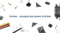
TotemBus building blocks
Main components of TotemBus are Baseboards and Functionboards. The general idea is that you can adapt the system to what you’re building — Functionboards are interchangeable parts that contains a set of unique functions, ranging from general purpose inputs/outputs to specialized servo, stepper motor drivers, sensors and so on.
Baseboards
Currently we have two types of Baseboards available: X2 and X3.

Baseboard X2
X2 Baseboards are used as a basic building block for the bus — each Baseboard connected to the bus works as a separate MQTT client with a unique set of control topics.

Baseboard X3
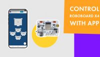
The X3 Baseboard extends the functionality further by also adding a Bluetooth interface. This allows any Bluetooth-enabled device such as a laptop, smartphone to wirelessly control all devices on the TotemBus. For example, you can use our Android app to pass messages to the bus.
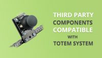
Function boards
Functionboard is a specialised extension to the Baseboard, containing hardware needed to achieve specific control task. They are all compatible with every Baseboard, so you can use any Functionboard with any Baseboard. Even more, you can change the Functionboard any time you like. Whenever you swap a Functionboard, it automatically get’s detected by the bus, which introduces it to the system. All that’s left to do for you is to assign a specific behavior rule for the new function. What came as a bonus is that everything is done on the fly, so there’s nothing to distract you from achieving your goals – no need to upload new code into the system, deal with compiler errors or wait for restarts.

Various function boards
We are starting with motor control function boards, but have many more in the pipeline.
That’s the basic overview of TotemBus. Next time we’ll go deeper into the MQTT protocol uses for controlling Functionboards from the smartphone app.